Home » Arduino Nano RP2040 Connect RGB led examples

Arduino Nano RP2040 Connect RGB led examples

by 2b4a3pico71

In this article we look at the RGB led which is fitted on the Arduino Nano RP2040 Connect

The RGB LED (DL3) is a common anode LED that is connected to the Nina W102 module. The LED is off when the digital state is HIGH and on when the digital state is LOW.

rgb led

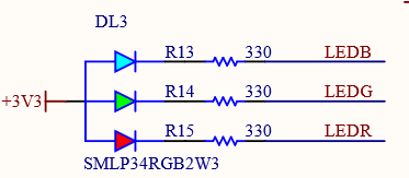
While using the BLE mode on the NINA module, the RGB cannot be used by default. While the module is in BLE mode, SPI is deactivated, which is used to control the RGBs.

We can see that the RGB led pins are connected to pins 16 to 18 on the UBlox NINA Module. So in order to use the RGB LED, we are going to have to go through this WiFi module.

ninapinout

Here is the physical location of the RGB led on the board

RGB-PIXEL-NANORP2040CONNECT


Parts Required


Name Link
Nano RP2040 Connect. Arduino Nano RP2040 Connect with Headers

Code Examples

You need to install the WifiNINA library

This must be installed from the Library Manager:

  • Click Tools -> Manage Libraries to open the Library Manager.
  • Search for WifiNINA and install the latest version of the library.

Blink the LED

Plain text
Copy to clipboard
Open code in new window
EnlighterJS 3 Syntax Highlighter
#include <WiFiNINA.h>
void setup()
{
// Set LED Pins as Outputs
pinMode(LEDR, OUTPUT);
pinMode(LEDG, OUTPUT);
pinMode(LEDB, OUTPUT);
}
void loop()
{
digitalWrite(LEDR,HIGH); // Turn On RED LED
delay(500);
digitalWrite(LEDR,LOW); // Turn Off RED LED
digitalWrite(LEDG,HIGH); // Turn On GREEN LED
delay(500);
digitalWrite(LEDG,LOW); // Turn Off GREEN LED
digitalWrite(LEDB,HIGH); // Turn On BLUE LED
delay(500);
digitalWrite(LEDB,LOW); // Turn Off BLUE LED
}
#include <WiFiNINA.h> void setup() { // Set LED Pins as Outputs pinMode(LEDR, OUTPUT); pinMode(LEDG, OUTPUT); pinMode(LEDB, OUTPUT); } void loop() { digitalWrite(LEDR,HIGH); // Turn On RED LED delay(500); digitalWrite(LEDR,LOW); // Turn Off RED LED digitalWrite(LEDG,HIGH); // Turn On GREEN LED delay(500); digitalWrite(LEDG,LOW); // Turn Off GREEN LED digitalWrite(LEDB,HIGH); // Turn On BLUE LED delay(500); digitalWrite(LEDB,LOW); // Turn Off BLUE LED }
#include <WiFiNINA.h>

void setup() 
{
  // Set LED Pins as Outputs
  pinMode(LEDR, OUTPUT);
  pinMode(LEDG, OUTPUT);
  pinMode(LEDB, OUTPUT);
}

void loop() 
{
  digitalWrite(LEDR,HIGH); // Turn On RED LED
  delay(500);
  digitalWrite(LEDR,LOW); // Turn Off RED LED

  digitalWrite(LEDG,HIGH); // Turn On GREEN LED
  delay(500);
  digitalWrite(LEDG,LOW); // Turn Off GREEN LED

  digitalWrite(LEDB,HIGH); // Turn On BLUE LED
  delay(500);
  digitalWrite(LEDB,LOW); // Turn Off BLUE LED
}


Fading LED

Plain text
Copy to clipboard
Open code in new window
EnlighterJS 3 Syntax Highlighter
#include <WiFiNINA.h>
int rgbRed = 0, dir=1;
void setup()
{
// Set the LED pins as outputs
pinMode(LEDR, OUTPUT);
}
void loop()
{
rgbRed = rgbRed + (1 * dir);
if(rgbRed > 255)
{
rgbRed = 255;
dir = -1;
}
if(rgbRed < 0)
{
rgbRed = 0;
dir = 1;
}
analogWrite(LEDR, rgbRed);
delay(5);
}
#include <WiFiNINA.h> int rgbRed = 0, dir=1; void setup() { // Set the LED pins as outputs pinMode(LEDR, OUTPUT); } void loop() { rgbRed = rgbRed + (1 * dir); if(rgbRed > 255) { rgbRed = 255; dir = -1; } if(rgbRed < 0) { rgbRed = 0; dir = 1; } analogWrite(LEDR, rgbRed); delay(5); }
#include <WiFiNINA.h> 

int rgbRed = 0, dir=1; 

void setup() 
{ 
// Set the LED pins as outputs 
pinMode(LEDR, OUTPUT); 
} 

void loop() 
{ 
rgbRed = rgbRed + (1 * dir); 
if(rgbRed > 255) 
{ 
rgbRed = 255; 
dir = -1;
} 
if(rgbRed < 0) 
{ 
rgbRed = 0; 
dir = 1; 
} 
analogWrite(LEDR, rgbRed); 
delay(5); 
}


Random LED colors

Plain text
Copy to clipboard
Open code in new window
EnlighterJS 3 Syntax Highlighter
#include <WiFiNINA.h>
void setup()
{
// Set the RGB pins to output
pinMode(LEDR, OUTPUT);
pinMode(LEDG, OUTPUT);
pinMode(LEDB, OUTPUT);
randomSeed(1);
}
void loop()
{
// sets the value (range from 0 to 255) for 3 RGB channels:
analogWrite(LEDR, random(255));
analogWrite(LEDB, random(255));
analogWrite(LEDG, random(255));
// wait for 500 milliseconds before changing the color again
delay(500);
}
#include <WiFiNINA.h> void setup() { // Set the RGB pins to output pinMode(LEDR, OUTPUT); pinMode(LEDG, OUTPUT); pinMode(LEDB, OUTPUT); randomSeed(1); } void loop() { // sets the value (range from 0 to 255) for 3 RGB channels: analogWrite(LEDR, random(255)); analogWrite(LEDB, random(255)); analogWrite(LEDG, random(255)); // wait for 500 milliseconds before changing the color again delay(500); }
#include <WiFiNINA.h> 

void setup() 
{ 
// Set the RGB pins to output 
pinMode(LEDR, OUTPUT); 
pinMode(LEDG, OUTPUT); 
pinMode(LEDB, OUTPUT); 
randomSeed(1); 
} 

void loop() 
{ 
// sets the value (range from 0 to 255) for 3 RGB channels: 
analogWrite(LEDR, random(255)); 
analogWrite(LEDB, random(255)); 
analogWrite(LEDG, random(255)); 
// wait for 500 milliseconds before changing the color again 
delay(500); 
}


You may also like

Adblock Detected

Please support us by disabling your AdBlocker extension from your browsers for our website.